Leave your message now to get your free sample and discount price
Choosing the right cutting tool can determine whether a machining operation becomes stable, costly, or unexpectedly difficult. Cemented Carbide Inserts remain a preferred solution because they combine high hardness with practical wear resistance. They cut hardened steels, cast iron, stainless steel, and many difficult alloys with consistent results.
Professor Erik O. Ståhl, a recognized machining researcher, has emphasized, “Tool performance depends on matching the cutting edge to the material and the process.” This principle sounds simple. It is not always easy to apply. A carbide grade that performs well on dry cast iron may fail quickly on interrupted stainless-steel cuts. Cutting speed, feed rate, coolant delivery, edge geometry, and machine rigidity all influence the result.
In a typical shop, an operator may inspect a worn insert under bright task lighting. A small crater on the rake face can reveal excessive heat. A chipped corner may point to vibration, excessive feed, or an overly brittle grade. These details matter more than attractive catalog claims.
Cemented Carbide Inserts can reduce tool changes and support predictable production, but they are not a universal answer. Selection still requires testing. Even experienced machinists sometimes choose a grade by habit, then discover that the workpiece material has changed. That mistake is worth acknowledging. Reliable machining comes from measured trials, controlled parameters, and careful observation of the cutting edge. This article examines why Cemented Carbide Inserts remain valuable, where their limits appear, and how informed selection can improve machining performance.
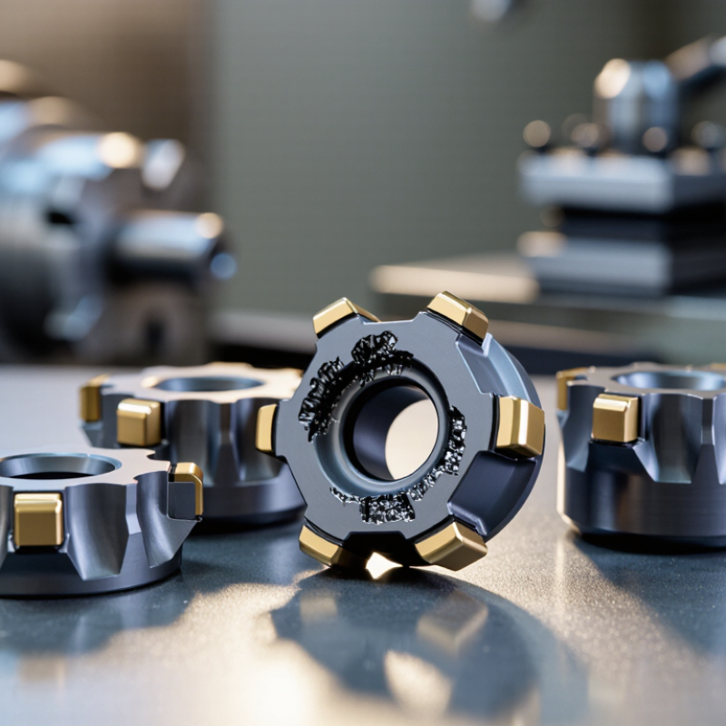
Cemented carbide inserts are replaceable cutting tips made from hard carbide particles held in a tough metal binder. In many grades, tungsten carbide provides wear resistance, while cobalt helps absorb shock. This combination supports turning, milling, and drilling at demanding cutting speeds. The insert is not simply solid carbide. Its performance comes from a carefully controlled composite structure.
Manufacturing begins with selected powders. Producers mill carbide and binder powders until the mixture reaches a consistent distribution. Small differences matter. The powder is then blended with pressing agents and compacted inside a die. The pressed shape is fragile, almost like chalk. It must be handled carefully.
Sintering heats the compact below carbide’s melting point. The binder flows and locks the particles together. The insert shrinks during this stage, so dimensional control is essential. Diamond grinding creates the final geometry, edge preparation, and tolerance. Some inserts receive a thin coating to reduce friction and chemical wear. In practical machining, the correct grade depends on workpiece material, interrupted cuts, coolant, and machine rigidity. A harder grade may resist abrasion but chip under impact. A tougher grade may survive vibration but wear sooner. That trade-off is easy to underestimate. Test cuts, measured wear, and operator experience still matter.
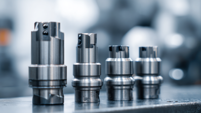
Cemented carbide inserts support reliable machining through hardness, stiffness, and controlled wear. Their tungsten-carbide structure retains cutting strength at elevated temperatures. That matters when a tool meets hardened steel, cast iron, or abrasive alloys.
The International Tungsten Industry Association estimates that cemented carbide consumes roughly 60% of global tungsten use. The U.S. Geological Survey reported about 81,000 metric tons of tungsten mine production in 2023. These figures reflect carbide’s industrial importance, not automatic performance. In practice, a stable insert depends on grade, edge preparation, coolant, and machine rigidity.
A carefully selected insert can reduce edge breakdown during long production runs. Its hardness helps maintain geometry while chips leave the cutting zone. Its cobalt binder adds toughness, although excessive heat can still weaken the cutting edge. ISO 1832 provides standardized insert designations, helping machinists match geometry with operating conditions. My shop-floor experience suggests that conservative speeds often produce more predictable results than aggressive catalog values. Still, this approach can waste cycle time. Operators should track flank wear, cutting forces, surface finish, and actual tool life. A shiny insert is not necessarily a healthy insert. Reliable machining comes from measured adjustments, not assumptions.
Typical cutting-speed ranges for turning carbon steel illustrate how carbide’s hot hardness supports faster machining than high-speed steel (HSS). Actual speeds depend on the workpiece, grade, operation, and setup.
Typical reference ranges: HSS, 20–40 m/min; cemented carbide, 80–200 m/min. These are indicative ranges, not guaranteed operating recommendations.
Cemented carbide inserts support turning operations where steady heat and long tool contact can quickly wear softer edges. Their hard carbide particles resist abrasion, while the metallic binder helps the edge withstand cutting forces. In a steel turning pass, this can mean a predictable flank-wear pattern and longer runs between tool changes. Small sentences matter. The U.S. Geological Survey’s Mineral Commodity Summaries 2025 estimated 2024 global tungsten mine output at 81,000 tonnes and identifies cemented carbides as a leading tungsten use, including metal-cutting tools.
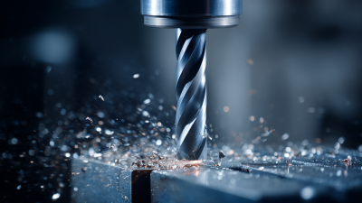
Milling benefits in a different way. Indexable inserts let operators replace one worn edge instead of discarding the whole cutter. That helps control downtime on face-milled plates or machined housings. Yet milling creates interrupted cuts, so edge toughness and the correct grade matter; a very hard edge can chip if setup vibration is poor. Not magic. Stable workholding and sensible feed rates still count.
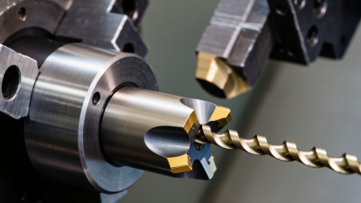
In drilling, carbide inserts can maintain cutting performance in high-volume holes, especially when chip evacuation and coolant delivery are well managed. Their wear resistance helps keep hole size more consistent over a production run. For heat-resistant alloys, however, heat buildup can shorten edge life, even with carbide. A practical trial should track tool life, surface finish, and insert cost per part—not just cutting speed. Carbide is not always the economical choice for short, occasional jobs.
Cemented carbide inserts are used to machine steel shafts, cast-iron housings, and stainless pump components. Their hard carbide grains, held in a metallic binder, help resist wear at the hot cutting edge. On a lathe, a suitable grade can maintain dimensions across a batch of valve bodies. Small details matter: chipbreaker shape, nose radius, cutting speed, and coolant can all change the result.
Different materials call for different insert designs. Cast iron often produces short, abrasive chips, while stainless steel can work-harden and generate heat. Aluminum usually needs a sharp edge and enough clearance to limit built-up material. Some nickel alloys need heat-resistant grades and careful feed rates. No universal choice. Composites and hardened materials may need specialized geometries, and selection should account for machine rigidity and workholding.
These tools serve automotive, aerospace, energy, agricultural equipment, and general manufacturing. A shop might turn axle parts, mill turbine components, or face heavy gear blanks. The practical benefit is predictable tool life, not magic. Interrupted cuts can chip a hard insert, especially with a loose setup. Setup matters. A short trial cut, followed by checking the edge and surface finish, often reveals more than a catalog chart.
When selecting a cemented carbide insert, match its grade to the workpiece, not just the machine’s maximum speed. ISO 513 groups cutting materials by application, including steel, stainless steel, cast iron, and hardened materials. These groups narrow the search, but they do not replace a test cut. A tough grade can resist interrupted cuts, while a harder, wear-resistant grade may last longer in steady finishing. There is a trade-off.
Geometry matters just as much. A sharp edge can reduce cutting forces on thin parts, but may chip if the setup vibrates. Check the holder, overhang, workholding, and coolant delivery before changing grades. ISO 3685 uses 0.3 mm average flank wear as a common tool-life test criterion for regular turning conditions. That is a useful benchmark, not an automatic shop-floor replacement limit. Real parts may fail from surface finish or dimensional drift first.
Track the details. Record material hardness, cutting speed, feed, depth of cut, and insert life across several parts. A short, controlled trial is more useful than changing several settings at once. Compare cost per acceptable part, not insert price alone. Honestly, one trial may still mislead; batch variation and operator adjustments can distort the result. Keep notes, then repeat under stable conditions.
| Why Choose Cemented Carbide Inserts for Machining? - Factors to Consider When Selecting an Insert for a Job | |||
|---|---|---|---|
| Selection Factor | What to Consider | Typical Guidance | Effect on the Job |
| Workpiece Material | Identify the material group, hardness, condition, and abrasiveness. Common groups include steel, stainless steel, cast iron, non-ferrous metals, and heat-resistant alloys. | Choose a carbide grade and cutting geometry intended for the workpiece material. Tougher or work-hardening materials may need a sharper edge and a more resistant grade. | Improves cutting stability and helps limit edge wear, built-up edge, and premature insert failure. |
| Operation Type | Determine whether the job involves continuous turning, interrupted cutting, facing, grooving, or milling. | Use a stronger edge preparation for interrupted cuts or heavy engagement. A sharper edge may be suitable for light finishing and lower cutting forces. | Matching the insert to the operation reduces chipping risk and supports consistent tool life. |
| Carbide Grade | Consider the balance between wear resistance and toughness, along with the stability of the machine and setup. | Wear-resistant grades are often selected for stable, higher-speed finishing. Tougher grades are commonly preferred for roughing, interrupted cuts, or less rigid setups. | A suitable grade helps balance productivity with resistance to fracture and gradual wear. |
| Coating | Coated carbide inserts use thin surface layers to influence wear resistance, heat resistance, and friction. Coating suitability depends on the workpiece and cutting conditions. | Common coating families include titanium nitride, titanium carbonitride, titanium aluminum nitride, and aluminum oxide. Select by application rather than coating name alone. | The right coating can slow wear and extend usable tool life; an unsuitable coating may not perform well in a particular material or operation. |
| Insert Shape and Included Angle | Consider how much edge strength is needed and whether the tool must access shoulders, contours, or confined areas. | Rounder or larger-angle shapes generally offer stronger cutting edges. Smaller-angle shapes can provide better access but may be less robust. | A shape suited to the cut improves accessibility while maintaining adequate edge strength. |
| Rake and Cutting Geometry | Choose geometry based on the required cutting force, edge strength, material behavior, and available machine power. | Positive-rake geometries typically cut with lower forces and suit lighter cuts. Negative-rake geometries generally provide a stronger edge and are often used with rigid setups. | Geometry affects power demand, heat generation, chip formation, and the likelihood of edge damage. |
| Chipbreaker | Match the chipbreaker to the feed, depth of cut, material, and operation. | Finishing chipbreakers are designed for lighter cuts; roughing chipbreakers are designed for heavier cuts. Follow the insert maker’s application range for the selected geometry. | Good chip control helps prevent long chips from damaging the workpiece, tool, or machine and supports safer operation. |
| Nose Radius | Balance required surface finish against cutting force, chatter tendency, and edge strength. | A smaller nose radius can support low-force finishing and tight profiles. A larger nose radius can strengthen the tip but may increase forces and vibration on a flexible setup. | The appropriate radius helps achieve the surface finish while maintaining stable cutting. |
| Cutting Data | Set cutting speed, feed, and depth of cut according to the insert grade, workpiece, operation, and machine capability. | Start with the cutting-data range recommended for the specific insert and material, then adjust using measured tool wear, chip shape, and surface finish. | Suitable parameters help control heat and wear while avoiding overload, poor chip breaking, or unstable cutting. |
| Machine and Setup Rigidity | Assess tool overhang, workpiece support, holder condition, spindle stability, and clamping. | Use a robust insert and conservative cutting conditions when the setup is prone to vibration. Reduce overhang and improve support where possible. | A rigid setup allows more predictable performance and reduces chatter, chipping, and inconsistent finish. |
| Cost per Part | Compare insert price with tool life, cycle time, changeover time, scrap risk, and the number of usable cutting edges. | Evaluate total machining cost under representative production conditions rather than choosing solely by purchase price. | A higher-cost insert may be economical if it reliably reduces cycle time, downtime, or rejected parts. |
| Cemented carbide inserts are valued for their hardness, wear resistance, and ability to machine a wide range of materials. Actual performance depends on the insert specification, workpiece, machine, setup, and cutting conditions; verify recommendations with the insert supplier’s technical data and controlled trials. | |||