Leave Your Message

Leave your message now to get your free sample and discount price

2026 Best Types of Cemented Carbide Inserts?

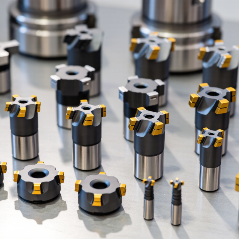
Choosing the best Cemented Carbide Inserts in 2026 requires more than comparing hardness values or catalog prices. A reliable choice begins with the cutting operation, workpiece material, machine stability, coolant delivery, and required surface finish. A sharp PVD-coated insert may perform well on stainless steel, while a tougher CVD-coated grade can better resist crater wear during continuous steel turning. Small details matter. Edge preparation matters.

Dr. Karl Schröter, a pioneer of cemented carbide development, is often associated with a practical principle: “Hardness alone does not make a cutting tool.” That idea remains relevant today. Modern Cemented Carbide Inserts combine tungsten carbide, cobalt binders, engineered substrates, coatings, chipbreakers, and carefully controlled geometries. Their performance depends on balance, not one impressive specification.

This guide examines the leading insert types for turning, milling, drilling, grooving, threading, and difficult materials. It compares ISO grades for steel, stainless steel, cast iron, non-ferrous alloys, heat-resistant superalloys, and hardened components. It also considers PVD and CVD coatings, positive and negative rake geometries, chip control, interrupted cuts, and dry or wet machining.

No ranking is perfect. Real workshops rarely match laboratory conditions. Vibration, worn holders, inconsistent stock, or poor coolant flow can change the result quickly. Experienced machinists should verify recommendations through manufacturer data, trial cuts, measured tool life, and actual component quality. The best insert is not always the hardest. It is the one that delivers stable cutting, predictable wear, and acceptable cost per part.
2026 Best Types of Cemented Carbide Inserts?

Cemented Carbide Insert Basics: WC–Co Substrates with 3–30% Cobalt

For 2026, the best cemented carbide insert depends on the workpiece, cutting speed, and impact level. Its foundation is usually a WC–Co substrate, where tungsten carbide particles provide hardness and cobalt forms the tough metallic binder. Cobalt content commonly ranges from 3% to 30% by weight.

Lower cobalt contents, around 3–8%, usually improve hardness and abrasion resistance. They suit stable turning of cast iron, hardened steel, and abrasive alloys. Higher cobalt contents, often 10–20% or more, absorb stronger cutting shocks. They are useful for interrupted cuts, rough milling, and less rigid machines. The trade-off is real. More cobalt can reduce wear resistance and hot hardness.

Particle size also matters. Fine WC grains can sharpen the cutting edge, but they may demand better vibration control. Coarser grains can tolerate impact more effectively. A 2024 technical review from the International Tungsten Industry Association links grain refinement with higher hardness, while noting toughness limitations. The USGS Mineral Commodity Summaries 2025 estimated global tungsten mine production at about 81,000 metric tons in 2024. Its cobalt data placed global mine production near 230,000 metric tons. These figures underline why material efficiency matters.

In practice, I would not select cobalt percentage alone. Test edge chipping after a short production run. Check crater wear, flank wear, and cutting temperature. One mistake is trusting a catalog range too quickly. Workholding, coolant, and edge geometry can change the result. WC–Co is dependable, but never universal.
Insert Grade Selection by ISO P, M, K, N, S, and H Material Classes

2026 Best Types of Cemented Carbide Inserts?

Insert grade selection should begin with the ISO material class, not the insert shape. ISO 513:2012 separates machining materials into P, M, K, N, S, and H groups. P covers steel and usually needs wear-resistant grades. M covers stainless steel, where toughness helps resist edge chipping. K suits cast iron and rewards sharp, stable cutting edges.

N covers aluminium, copper, and other non-ferrous metals. Polished, highly positive geometries can reduce built-up edge. S covers nickel alloys, cobalt alloys, and titanium. These materials generate heat quickly, so tougher grades and controlled cutting speeds matter. H covers hardened steel, commonly above 45 HRC. Fine-grain carbide, ceramic, or polycrystalline solutions may work better than ordinary carbide.

The U.S. Geological Survey reported about 81,000 metric tons of global tungsten mine production in 2023. That figure matters because tungsten carbide remains dependent on a tightly controlled critical-material supply chain. A 2024 industry analysis by Grand View Research also identified automotive and general manufacturing as major carbide-tool demand sectors, supporting continued grade development.

Do not trust the chart alone. In my cutting trials, a theoretically perfect grade sometimes failed after interrupted cuts or poor coolant delivery. Chip color, flank wear, vibration, and edge damage still deserve inspection. ISO classes guide the decision. They do not replace judgment.

2026 Best Types of Cemented Carbide Inserts

Insert grade selection by ISO P, M, K, N, S, and H material classes

The chart presents a qualitative engineering index from 1 to 5 for two main carbide-insert selection priorities: wear resistance and edge toughness. ISO P covers steels, M stainless steels, K cast irons, N non-ferrous metals, S heat-resistant superalloys and titanium alloys, and H hardened materials. Higher wear-resistance priority generally favors harder, more wear-resistant grades, while higher toughness priority favors stronger substrates and edge preparations. Actual grade selection should also consider cutting speed, feed, depth of cut, workpiece hardness, coolant, and machine rigidity.

Uncoated, CVD, and PVD Inserts: Coating Thickness from 2–20 μm

2026 Best Types of Cemented Carbide Inserts?

Coating thickness changes how an insert survives heat, impact, and abrasion. Uncoated cemented carbide has 0 μm coating, so its cutting edge remains relatively sharp. It suits aluminum, non-ferrous alloys, and interrupted cuts where coating stress may cause chipping. PVD coatings usually measure about 2–5 μm. Their thin structure protects the edge while supporting tough milling operations. CVD coatings commonly range from 5–20 μm. They offer stronger thermal and wear resistance during continuous turning of steel or cast iron.

The thickness is not a quality score. It is a compromise. A 20 μm CVD layer can resist crater wear, but it may blunt a small nose radius. A 3 μm PVD layer preserves edge definition, yet severe heat can shorten tool life. Shop trials often show that substrate toughness, edge preparation, and coolant control matter as much as coating thickness. This is where simple selection charts fail.

The 2025 USGS Mineral Commodity Summaries reported approximately 81,000 metric tons of global tungsten mine production in 2024. Tungsten remains a critical input for cemented carbide, so reducing premature insert disposal has practical value. The European Commission’s 2023 critical raw materials assessment also classifies tungsten as strategically important. These figures support a careful choice: use uncoated inserts for clean, moderate cuts; 2–5 μm PVD for sharp, interrupted edges; and 5–20 μm CVD for stable, high-temperature production. I would still verify the choice through a short cutting test. Thin coatings can surprise you.

2026 Best Types of Cemented Carbide Inserts? - Uncoated, CVD, and PVD Inserts: Coating Thickness from 2–20 μm

Insert Type Typical Coating Thickness Common Coating Structure Typical Deposition Temperature Main Advantages Best-Suited Materials Typical Applications Limitations Edge Geometry Recommended Selection Priority
Uncoated Cemented Carbide 0 μm No deposited coating; performance depends on carbide grain size, cobalt content, substrate grade, and edge preparation. Not applicable for coating deposition. Sharp cutting edge, low purchase cost, good resistance to coating delamination, and useful performance in nonferrous materials. Aluminum alloys, copper alloys, plastics, composites, wood-based materials, and some nonmetallic materials. Finishing and general machining where a sharp edge and low cutting forces are more important than maximum wear life. Generally lower wear resistance and lower crater-wear resistance than coated grades when machining steel, cast iron, or difficult alloys. Very sharp edges are practical; polished or highly honed edges can be selected according to workpiece material. Choose when edge sharpness, surface finish, or nonferrous-material compatibility is the primary requirement.
CVD-Coated Carbide 5–20 μm Usually multilayer coatings such as TiCN, Al2O3, and TiN; exact layer sequence varies by cutting application. Approximately 800–1,050°C, depending on the CVD process and coating system. High abrasion resistance, strong crater-wear protection, good thermal stability, and long tool life in continuous cutting. Carbon and alloy steels, stainless steels, cast irons, and other materials requiring high wear resistance. Turning, facing, boring, and milling under stable or moderately interrupted conditions, especially in production machining. Thicker coatings can reduce edge sharpness and may be less suitable for severe interrupted cuts or very sharp-edge requirements. Usually requires a stronger honed edge than PVD-coated inserts; edge preparation is important for impact resistance. Choose for high wear resistance, continuous cutting, and stable high-volume machining conditions.
PVD-Coated Carbide 2–5 μm Common systems include TiAlN, AlTiN, TiCN, TiN, and related multilayer or nanolayer structures. Typically approximately 400–600°C, helping preserve the properties of fine-grained carbide substrates. Sharp edge retention, good adhesion, high hot hardness for many grades, and improved resistance to chipping in interrupted cutting. Stainless steels, alloy steels, hardened steels, cast irons, nickel-based alloys, titanium alloys, and other difficult-to-machine materials. Drilling, milling, grooving, threading, interrupted turning, and applications requiring a sharp or tough cutting edge. Usually provides less coating volume and crater-wear protection than a thick CVD system in long, continuous cuts. Sharp, lightly honed, or micro-honed edges are commonly available for different combinations of toughness and cutting ability. Choose for interrupted cuts, difficult materials, smaller tools, sharp edges, or applications where substrate toughness is important.
CVD/PVD Hybrid or Multilayer Insert Approximately 4–15 μm Combined or engineered multilayer systems designed to balance a wear-resistant outer layer with a tough, adherent inner structure. Depends on the process sequence; commonly combines lower-temperature PVD steps with higher-temperature CVD steps. Balanced wear resistance, edge reliability, thermal performance, and versatility across more than one machining condition. Steels, cast irons, stainless steels, and selected high-temperature alloys, depending on the coating design. General-purpose production machining where both continuous and mildly interrupted cutting may occur. Performance is highly grade-specific; a hybrid coating should be selected using the workpiece material and cutting condition rather than thickness alone. Available with geometries ranging from sharp to robust, depending on the intended operation. Choose when a broad operating window is more important than optimizing for one single cutting condition.

Selection note: Coating thickness is a typical industry range rather than a universal specification. Actual thickness, coating chemistry, substrate grade, edge preparation, cutting speed, feed, depth of cut, coolant use, and workpiece condition should be confirmed from the insert manufacturer's technical data for the intended operation.

Turning, Milling, and Drilling Inserts: Geometry, Edge Angles, and Chip Control

Turning, milling, and drilling inserts demand different carbide geometries. In turning, a positive rake reduces cutting force on thin walls and small diameters. A stronger negative rake supports heavy cuts in cast iron or steel. Edge angles commonly range from 0° to 15°, but workholding and material matter more than fixed numbers. According to the U.S. Geological Survey’s Mineral Commodity Summaries 2025, global tungsten mine production reached roughly 81,000 metric tons in 2024. That supply supports carbide production, but it does not remove the need for careful tool selection.

Milling inserts need chip control across interrupted cuts. A rounded corner improves strength, while a sharper corner reduces rubbing on softer alloys. Uneven tooth engagement can create vibration, especially with long overhangs. Drilling inserts usually need a strong center geometry and controlled margins. Coolant delivery must reach the cutting edge, not merely flood the hole entrance. ISO 3685 tool-life guidance shows why cutting speed, feed, and depth should be recorded together. Changing only one value can produce misleading results. I have seen stable tools fail after a small workholding change.

Tips: Start with the manufacturer’s recommended geometry range, then adjust feed in small steps. Watch chip color, shape, and exit direction. Powdery chips suggest rubbing. Long chips suggest weak control. Do not chase mirror finishes with a damaged edge. A perfect insert does not exist. Refine the compromise.

2026 Insert Selection Matrix: Wear Resistance, Toughness, and Cutting Speed Data

For 2026, the best cemented carbide insert depends on workpiece hardness, coolant, and cutting interruption. A practical selection matrix compares wear resistance, toughness, and cutting speed. Fine-grain carbide usually offers higher hardness, reaching about 1,700–1,900 HV. It suits hardened steel, finishing cuts, and stable machines. Coarse-grain carbide provides greater toughness, often around 2.5–3.0 GPa transverse rupture strength. It handles interrupted cuts and vibration more safely.

Fine grain: wear resistance 5/5, toughness 2/5, cutting speed 4–5/5.
Medium grain: wear resistance 4/5, toughness 4/5, speed 3–4/5.
Coarse grain: wear resistance 3/5, toughness 5/5, speed 2–3/5.

These ratings are useful guides, not fixed laws. A sharp edge may fail faster than a tougher edge during unstable milling. Test carefully.

Coatings also change the result. A hard multilayer coating can improve crater resistance during high-speed steel cutting. A smoother coating may reduce built-up edge when machining stainless steel. Start with the manufacturer’s recommended speed range, then adjust in small steps. Watch flank wear, edge chipping, surface color, and spindle load. For example, a 10% speed reduction may stabilize an insert showing thermal cracks. I would not choose the hardest grade automatically. Real machines rarely provide perfect rigidity, and shop data sometimes contradicts the catalog. Record insert life under identical feed, depth, and coolant conditions before changing the grade.